SENNETT SECURITY U.S. FLAG STICK DETAILS
|
|||||||
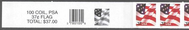
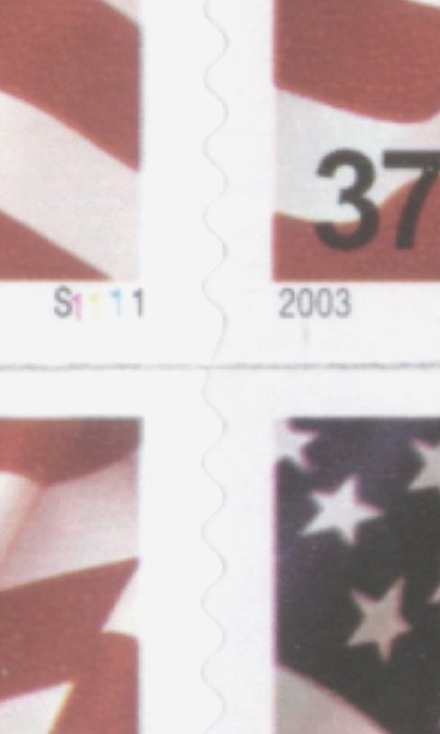
| This leader strip, from plate S1111, which also serves as the wrapper around the coil, is glued to the back of the coil. The leader is 179mm or about 7 inches long and extends 2 1/2 stamps into the coil. The left end of the strip is glued to itself in the space just to the left of the first stamp. Connecting bridges can be found on some leader strips. | |||||||
 |
|||||||
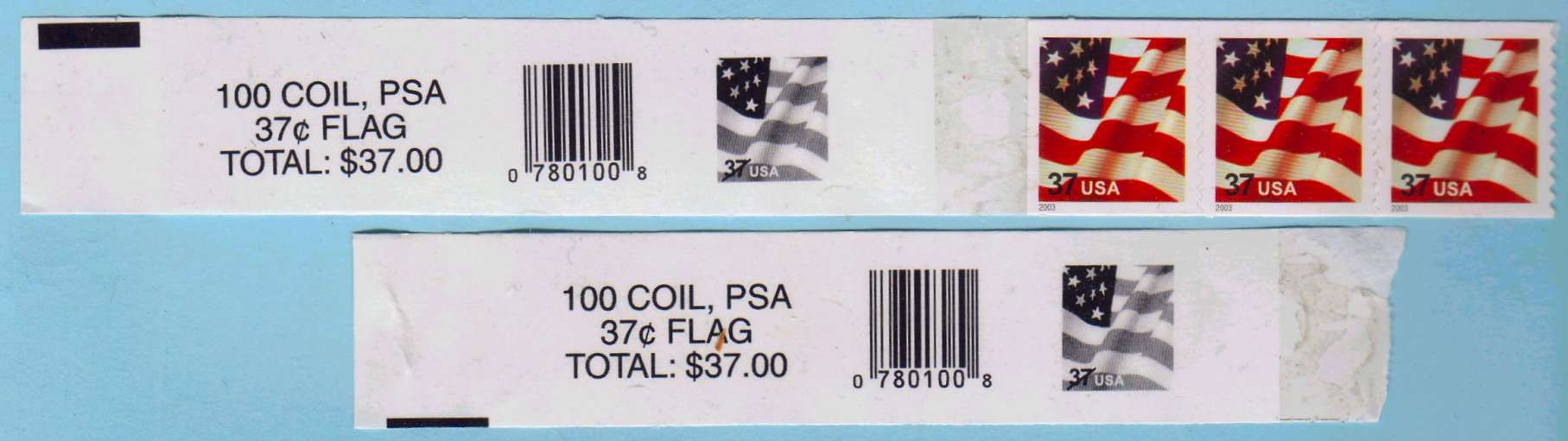
| These leader strips, from the plate S3333 printing, have horizontal rectangles on some of the 10 coils in the stick. The full black bars measure about 3 mm x 12 mm. It appears that the strips might be a little longer than the first printing, but I have not been able to examine the actual strips yet. The scan was provided by Dr. Robert Rabinowitz. | |||||||
 |
|||||||
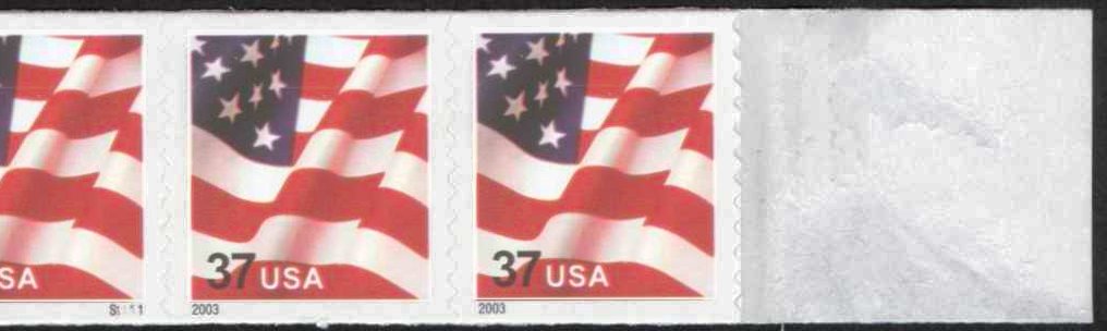
| The trailer strip is 85mm long and is glued to the end of the coil and starts 2 1/2 stamps from the end of the coil with 27mm extending beyond the end of the coil. The trailer is glued to itself on the inside of the coil. | |||||||
 |
|||||||
| On plate S1111, the bridges are 121mm (approximately 4 1/2 inches) apart. The bridges repeat about every 5 1/2 stamps. | |||||||
 |
 |
||||||
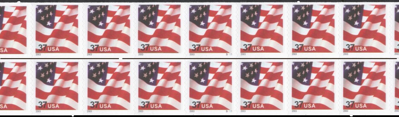
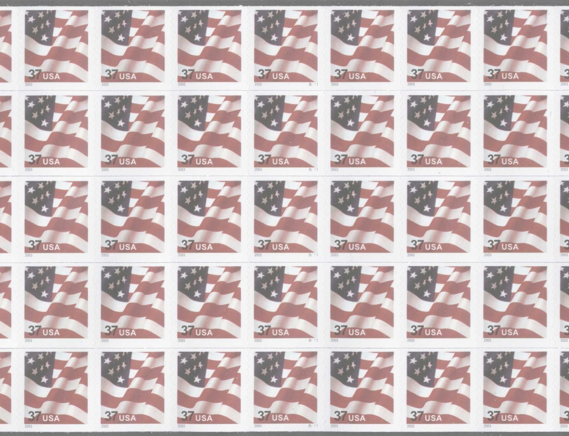
| On plate S3333, the bridges are about 60mm (approximately 2 3/8 inches) apart. The bridges repeat about every 2 1/2 stamps. | |||||||
| Click on any of the photos for a larger scan. The scans have been digitally altered to make the bridges clearer. | |||||||
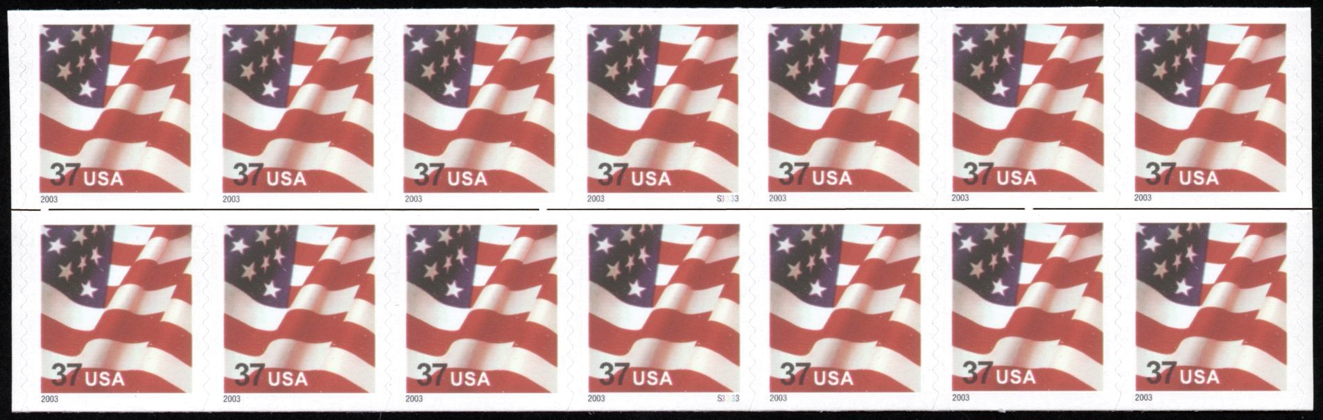
The
above scans (left side) illustrate the bridges between the coil rows that hold them together.
The right scan shows the vertical die cutting. Click on the photos for a larger,
more detailed scan.
|
|||||||
| These
stamps are being supplied to post offices in a stick of 5
and 10 coils. There are connecting bridges between each row to hold the coils
together inside the stick. The bridges are also on the leader strips on some coils. I have not been able to determine a pattern as to the placement of the bridges in various rows in relation to bridges on other rows. I'm not familiar with the process used to create these bridges. It's possible that the coils were slit with a wheel that had a break in it to allow for the bridge. It would be interesting to know how they created the bridges. |
|||||||
 |
|||||||
| Because
of the bridges, it is possible to create a block of attached vertical coils as I have done
above. Depending on the placement of the bridge, vertical pairs or blocks of 4 can
easily be created. Click on the above scan for more detail. |
|||||||